

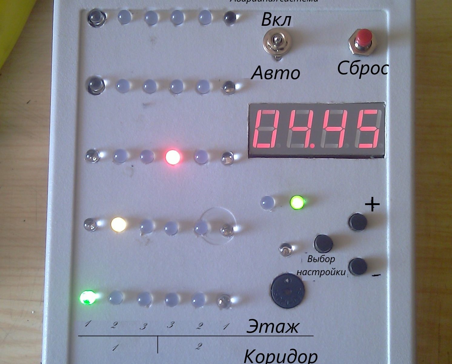
The System is a comprehensive hardware-software complex designed to automate firefighter training sessions within a heat and smoke training chamber.
Heat and Smoke Training Facility Overview
A heat and smoke training chamber is a specially equipped facility that simulates the extreme conditions of an interior structure fire. The facility is equipped with a training maze—a structure measuring 10 meters in length, 3 meters in width, and 2.5 meters in height. This structure is divided in half by one vertical partition and features two horizontal partitions. This configuration creates six interconnected “corridors” separated by walls with various crawl spaces and passageways. The maze has a single entry and a single exit point. The facility is additionally equipped with a high-capacity smoke generator and a heating unit to simulate heavy smoke logging and extreme temperatures.

Training Process
Following a predefined training plan, a trainee squad—specifically a Breathing Apparatus (BA) Team—enters the prepared facility wearing Self-Contained Breathing Apparatus (SCBA). Because the air supply in the SCBA is strictly limited, the team must navigate the maze and find the exit within a specific timeframe. The team’s movement occurs in confined spaces under conditions of zero visibility (dense smoke) and high heat.

System General Specifications
The automation system provides real-time tracking of personnel locations and automatically manages the facility’s emergency power units—specifically the emergency lighting, smoke extraction damper, and smoke exhaust fan. This significantly increases the safety margins of the training exercises.

The emergency systems can be activated in either manual or automatic mode. In manual mode, the instructor overseeing the drill can trigger the systems at any time. The automatic mode provides two fail-safe triggers:
- If a trainee stops moving for a preset number of seconds (a “man down” scenario where a trainee may require immediate rescue).
- If the team remains inside the maze longer than the allocated maximum time limit (indicating they failed to find the exit and their SCBA air supply is critically low).
When the automatic safety system triggers, it is accompanied by an audible alarm and a flashing indicator pinpointing the trainee’s last known location.
The activation of the high-voltage power relays is indicated by an LED (8) wired directly into the power-switching circuit, confirming that the load-switching components are fully operational.
The system initiates tracking automatically the moment a person enters the smoke chamber.
Additionally, during startup or reset, the system polls all position sensors. If a malfunction is detected, it outputs an error message and highlights the exact location of the faulty sensor.
Upon the team’s entry into the chamber, all preset training parameters are written to non-volatile memory (EEPROM). When the system is rebooted or reset, these values are restored, eliminating the need for the instructor to repeatedly input the same parameters for back-to-back exercises.

System Startup Procedure
To commission the system for operation:
- Connect the 15-pin male connector of the sensor signal cables to the main signal port (2).
- Connect the load cables (terminals 1-7) strictly according to the electrical wiring diagram.
- Connect the AC mains supply and the smoke damper power lines to terminals 8 and 9.
- Apply power to the AC mains supply.
! ! ! WARNING ! ! ! All high-voltage connections must be made exclusively while the AC mains supply is completely de-energized.
System Operation & Data Input
For the system to function correctly, parameters matching the specific training drill must be inputted.
Data input involves setting three configurable parameters. For ease of use, the currently selected parameter is highlighted brightly on the primary display (6). Immediately upon power-up or reset, the first parameter—the number of active tracking zones—is displayed on the location indicator (1). Adjusting this parameter does not illuminate the status indicator LEDs (7).
To cycle through the configurable parameters, press the “B” button (9).
The second parameter sets the “no-movement timeout” (in seconds). If the team remains stationary for this duration, the emergency systems will engage. Moving to a new zone resets this timer. The display (6) will show `0._ _` (where `_ _` is the previously saved value, adjustable from 0.01 to 0.60). Adjusting this parameter illuminates the right LED on the status indicator (7).
The third parameter sets the total drill time limit (in minutes). This is a strictly decreasing countdown. Once it expires, the emergency systems engage automatically. The display (6) will show `_ _.00` (adjustable from 01.00 to 90.00). Adjusting this parameter illuminates the left LED on the status indicator (7).
After the parameters are configured, the trainees enter the chamber. The system begins processing and displaying their real-time location while monitoring the countdown timers. If either timer (no-movement or total time) expires, the emergency evacuation systems are triggered. Normal operation is accompanied by dynamic updates on the status indicator (7).
Throughout the drill, the instructor monitors the team’s location. Once the team reaches the exit and their safe egress is visually confirmed, the instructor presses “Reset” to return the system to its initial state (or flag a sensor error if one occurred).
In the event of a sensor fault, the short circuit or broken sensor must be repaired, followed by a “Reset”. Once all faults are cleared, the system returns to the parameter selection screen (standby mode).
A diagnostic test program can be launched during startup. To do this, hold down the “Reset” button simultaneously with any of the control buttons (9), release “Reset”, and once the diagnostic animation begins, release the control button. Pressing “Reset” again will return the system to standby mode. *Note: Each control button triggers a different diagnostic animation (e.g., a scrolling marquee).*
Data Output
Information is routed to the location indicator, status indicator, and time display. The location indicator uses three distinct colors corresponding to the different vertical levels (floors) inside the training maze.
Audio Signals
System operations and critical events are duplicated via audible alerts.
Upon power-up or reset: One beep.
Upon team entry into the chamber: Two beeps.
In case of a hardware error: Three beeps.
Upon automatic triggering of the emergency systems: Continuous 0.7-second beeps with 0.7-second intervals.
Electrical Wiring Diagram (High-Voltage Section)

1-3: Smoke Damper Control
4-7: Lighting and Smoke Exhaust Fan Control
4 – Exhaust Fan “Neutral” (N)
5 – Exhaust Fan “Line” (L)
6 – Lighting “Neutral” (N)
7 – Lighting “Line” (L)
8, 9: System and Smoke Damper AC Mains Power (Wired in parallel)
8 – “Neutral” (N)
9 – “Line” (L)
R&D and Prototyping
After gathering the initial requirements and operational logic, an early prototype was built around an Atmega64A microcontroller.

The original firmware for this prototype was written entirely in AVR Assembly (AVR ASM).
Following successful laboratory tests, custom printed circuit boards (PCBs) were designed for the main controller and the display matrix. The final production board transitioned to an Atmega16A MCU, and the firmware was ported and optimized accordingly.


Project Approbation & Media Coverage
- The system is actively deployed in the training curriculum by the Department of Service Organization and Training at the National University of Civil Defence of Ukraine.
-
“Vremya” Newspaper: “In the dark and cramped, with screams and explosions”. Journalist Yana Tarasenko. Published on Sept 1, 2012.
-
“Fora” TV Channel. “Kharkiv News”: “Profession: Rescuing People. NUCZU prepares those who will free victims from fiery captivity.” Journalist Marina Demyanova.
-
“Simon” TV Channel. “Objective” News: “Rescuers will be accustomed to ‘field conditions’ from the student bench.” Journalist Ksenia Bai.
-
ATN News. Web Portal: “How future rescuers are trained.” Journalist Oksana Nechiporenko.
-
Ukrainian journalists, alongside NUCZU rescuers, navigated the mazes of the BA training complex.

