

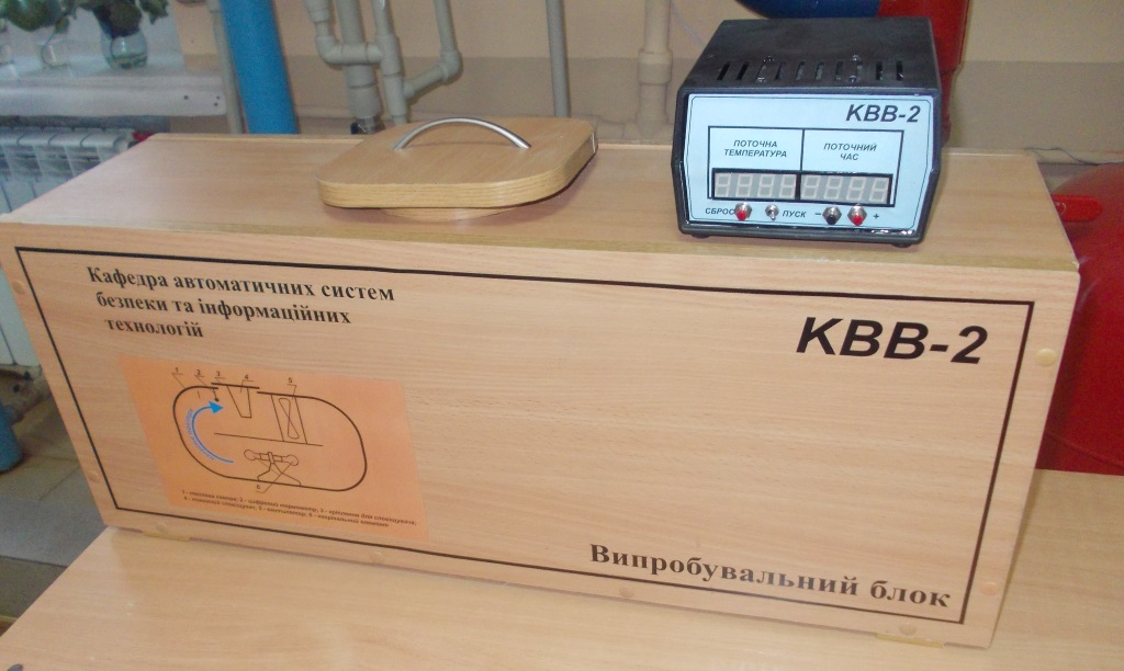
The Heat Fire Detector Testing Unit (KVV-2) is a portable hardware-software complex designed for testing point heat fire detectors (HFD) across a wide range of initial parameters (baseline temperature and rate of rise) with automated data logging. It enables testing of HFDs for compliance with EN 54-5:2000 (Fire detection and fire alarm systems. Part 5: Heat detectors – Point detectors). Furthermore, the unit allows input parameters to be set over a broader range than specified in the standard, facilitating deep-dive R&D research into detector characteristics. The system supports testing for both current-consuming and dry-contact heat detectors.
Overview
The system is a comprehensive hardware and software solution physically divided into two main components: the test chamber and the control unit.
Test Chamber

The test chamber is an enclosed aerodynamic loop where fans ensure continuous air circulation. Air is heated using incandescent lamps acting as heating elements, while temperature measurements are captured by a high-precision DS18B20 digital thermometer. The unit provides variable control over the airflow velocity inside the chamber. Structurally, the chamber is divided into upper and lower sections: the upper section houses the detector and measures the circulating air temperature, while the lower section is dedicated to heating. This dual-chamber design minimizes the direct radiant heat impact of the lamps on both the temperature sensor and the HFD under test. Preliminary R&D tests demonstrated that incandescent lamps offer lower thermal inertia and are much easier to replace in case of failure. The inner chamber is constructed from sheet metal coated with thermal insulation, while the outer shell is made of particleboard to provide mechanical rigidity and aesthetic appeal.

Control Unit
The control unit handles the input of initial conditions, measures chamber temperature, logs the response time (from reaching the baseline temperature to HFD activation), controls fan RPM, monitors the electrical state of the tested HFD, manages the heating elements using PID-like logic to maintain required temperatures and growth rates, and finally logs all experimental data.

A DS18B20 digital thermometer was selected for its sufficient temperature range, high precision, and excellent long-term stability. The heating control circuit utilizes TRIACs with complete galvanic isolation from the main MCU board, significantly improving the unit’s durability and maintainability. An interface module expands the unit’s capabilities to support various types of HFDs (current-loop or dry-contact). The system is powered by an Atmega8A microcontroller, which provides ample resources for the core functionality while leaving overhead for future feature expansion. The firmware was written in C (CodeVisionAVR) and debugged using AVR Studio 4.19. While hardware emulation in Proteus was attempted during the early design phase, it proved unreliable due to inadequate thermal modeling (MCU behavior in the emulator significantly differed from real-world physics). As is typical for early-stage R&D prototypes, the initial circuit was assembled and tested on a breadboard.

Experimental Results & Calibration
According to standard testing methodology, the unit must accurately reach the baseline temperature, hold it for a specific duration, and then begin ramping up the temperature at a strictly controlled rate.
Upon reaching the target baseline temperature, the unit exhibits a very minor temperature overshoot, which falls well within the tolerances permitted by the EN standard.

The temperature ramp-up occurs with highly acceptable deviations. The chart below demonstrates the reference (ideal) linear growth rate versus the actual temperature curve logged during physical measurement.

Functional Capabilities
Supported Point Heat Detector Types:
- Fixed-temperature (Maximum)
- Rate-of-rise (Differential)
- Combination (Fixed-temperature / Rate-of-rise)
Testing Modes:
- HFD thermal soaking at a given static temperature.
- Temperature ramp-up at a specified constant rate of rise.
Real-Time Display Data:
- Current chamber temperature.
- Elapsed time (in seconds) since reaching the baseline temperature.
- Current operating mode of the heating element.
Data Logged Upon Detector Activation:
- Exact activation temperature.
- Elapsed time from baseline temperature lock to detector activation.
Technical Specifications
- Power Supply: 220 V, 50 ± 5 Hz
- Power Consumption: Up to 1 kW (depending on installed heating elements)
- Test Chamber Cross-Section: 170 x 120 mm
- Airflow Velocity Range: 0.1 – 1.2 m/s
- Temperature Control Range: From ambient room temperature up to 125 °C (Accuracy: ± 1.0 °C)
- Temperature Measurement Resolution: ± 0.065 °C
- Temperature Rate of Rise (RoR) Range: 0 to 30 °C/min (Step: 0.1 °C/min)
- Baseline Temperature Soak Time: 1 minute


Project Validation & Approbation
- This unit was the core practical component of the Master’s thesis: “Experimental Setup for Testing Heat Fire Detectors”.
- Published in the scientific journal “Problems of Fire Safety”, Issue 29, 2011. “Apparatus for testing heat fire detectors”.
- Awarded a professional diploma and financial grant from the company “Brandmaster”.
- Successfully demonstrated at multiple scientific and technical engineering exhibitions.
Acknowledgments
- To the amazing team at the Department of Automatic Security Systems and Information Technologies at the National University of Civil Defence of Ukraine (NUCZU).
- To Stanislav, a mentor to whom I owe much, including my initial push into the world of microcontrollers.